
Quick Summary
When an automated gate stops operating, systematic LiftMaster LA500 control board troubleshooting prevents costly, unnecessary board replacements by first isolating external power drops, misaligned safety sensors, and blown fuses. The technical team at Ironworks Gate Co. recommends evaluating LED diagnostic blink counts, testing voltage under active motor load, and performing a full 15-second power reset before condemning hardware. Readers will learn how to safely isolate common fault codes like Code 53 and determine when to call certified technicians for same-day professional diagnostics and repairs.
LiftMaster LA500 Control Board Troubleshooting Guide
When an automated driveway gate suddenly stops moving, jumping straight to replacing the logic board is an expensive mistake. On the LiftMaster LA500, a flashing diagnostic LED or an unresponsive arm often points to a blown fuse, a misaligned photo eye, or a power issue rather than a dead circuit board.
As recommended by technicians at Ironworks Gate Co., before replacing a board, you need to check incoming power, inspect circuit protection, and test the system. This guide walks through the documented steps to read error codes, test board voltage, and isolate faults systematically.
Warning: Voltage and continuity testing should be performed only by a qualified person because the system contains hazardous voltage.
Essential Tools and Preliminary Checks
Accurate LiftMaster LA500 control board troubleshooting requires testing components while the motor attempts to run. Testing line voltage or battery terminals while the gate sits idle often gives false confidence, because a failing power supply can show normal static voltage right up until the arm demands current.[2]
Required Diagnostic Tools
- Digital multimeter capable of measuring DC voltage, AC voltage, and continuity
- Replacement fuses matching the specified type and rating
- Insulated 1/8-inch flathead terminal screwdriver
- Insulated work gloves
Quick Diagnostic Workflow
- Read the LED display: Note the error code numbers or diagnostic LED blink counts before turning off power.
- Check power and battery supply: Measure voltage across power and battery connections during gate operation.
- Power cycle: Cut all AC and battery power for 15 seconds to let the processor fully discharge and reboot.
Step 1: Read the Diagnostic LED Error Codes and Blink Counts
The LA500 control board features a diagnostic LED display alongside status lights. When the gate stops responding or reverses unexpectedly, diagnostic blink counts and board fault categories narrow down whether the issue lives in incoming power, safety inputs, or the board processor itself.[3]
Common LA500 Diagnostic Indicators
- Code 53 (Brownout Condition): Indicates an AC/DC supply brownout condition and warrants reviewing the power supply and wiring. Low or dead batteries are documented possible causes when operating on battery power.
- Internal Hardware Codes (Board Fault Categories): Codes indicating current-sense motor-control faults (FET), memory check failures (RAM, EEPROM), or watchdog timeouts point to board-level component failure. Disconnect all power, wait 15 seconds, reconnect power, and replace the main control board if the problem persists.
Step 2: Test Power Supply and Battery Voltage
A static multimeter reading may not reveal power delivery issues. A weak power supply or battery source can read normal voltage while at rest, but drop significantly under motor load, triggering a reset or Code 53 brownout condition.
Testing Power Under Operation
- Set your multimeter to DC volts and place the probes on the power or battery terminal connections at the board.
- Command the gate arm into motion.
- Observe the meter display when the motor engages.
- Evaluate the reading: Code 53 indicates a supply brownout and warrants reviewing the power supply and wiring. When operating on battery power, low or dead batteries are documented possible causes.
Step 3: Inspect Fuses and Power Feeds
Need liftmaster la500 control board troubleshooting?
We’re available now - call for a fast, free estimate.
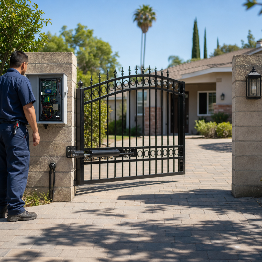
When the control board is completely dark with no LED activity, possible causes include no power, an open fuse, low or dead batteries, or a defective board.[1]
Testing Fuses
- Disconnect all AC and battery power from the operator.
- Inspect or test fuses for continuity using a multimeter set to continuity mode (or ohms). A good fuse shows continuity; an open fuse shows no continuity.
- Replace any blown fuse only with a fuse of the specified type and rating.
Checking for Physical Board Damage
Visually inspect the circuit board for signs of damage, such as discolored traces, damaged capacitors, or burn marks. If board-level faults persist after a full reset, the documented procedure is to disconnect all power, wait 15 seconds, reconnect power, and replace the main control board if the problem persists.[4]
Step 4: Check Monitored Safety Sensors
Modern LiftMaster LA500 boards monitor safety sensors in accordance with UL 325 standards. If the board does not receive a verified signal from monitored safety sensors, it prevents gate operation.
According to installation specialists at Ironworks Gate Co., verify that photo eyes and safety sensors have power, are clean, unobstructed, and properly aligned according to manufacturer instructions. Check sensor wiring for loose connections or damage.
Step 5: Reset the Control Board and Address Travel Limits
Temporary brownouts or faults can cause the microcontroller to freeze. Performing a structured 15-second power reset resolves many temporary conditions.
Documented Power Cycle Reset
- Switch off the primary AC power supply feeding the operator.
- Unplug the backup battery harness from the control board.
- Wait 15 seconds to allow the board to fully power down.
- Reconnect power to the board.
Clearing Stored Error Code History
To clear the diagnostic fault log from memory, press and hold the red STOP button on the board for roughly six seconds. The LED display will alternate between “Er” and “CL” to confirm that past error codes have been wiped clean.
Travel Limits
Note: Detailed recalibration procedures involving specific SET OPEN, SET CLOSE, and cycle sequences are unsupported by the primary documentation. Refer to the applicable operator installation manual for verified limit-setting instructions.
Step 6: Repair Wiring or Replace the Control Board
The manuals, along with technical guidance from Ironworks Gate Co., identify power, fuse, battery, accessory, and control-board faults as possible causes of operator malfunction.
Resolving Common Faults
- Replace an open fuse with one of the specified type and rating.
- Correct power supply, wiring, or low/dead battery issues.
- Clean, align, and verify monitored safety sensors.
When Board Replacement Is Necessary
If board fault categories or system errors continue, follow the documented procedure: disconnect all power, wait 15 seconds, reconnect power, and replace the main control board if the problem persists.
Frequently Asked Questions
How do you reset a LiftMaster LA500 control board?
To perform a full power reset, disconnect all AC power and unplug the backup battery harness. Wait 15 seconds, then reconnect power. To clear the stored error code log, press and hold the STOP button for approximately six seconds until the display flashes “Er” and “CL”.
Why is my LiftMaster LA500 not responding to any open or close commands?
A completely unresponsive board with no display activity can be caused by no incoming power, an open fuse, low or dead batteries, or a defective control board. Disconnect power, test fuses for continuity, check power connections and batteries, and follow documented reset procedures.
What does Code 53 mean on the LA500 display?
Diagnostic Code 53 indicates an AC/DC supply brownout condition and warrants reviewing the power supply and wiring. When operating on battery power, low or dead batteries are documented possible causes.
Can bad backup batteries prevent the gate from opening even with AC power connected?
When operating on battery power, low or dead batteries are a documented cause of power failure and brownout conditions (Code 53). Always ensure the power supply, wiring, and batteries are properly maintained.
How do you know if limit issues or the control board are causing travel errors?
Inspect the actuator arm wiring harness and check the physical connections and limit devices. If the board fails to respond or reports persistent internal board faults after performing the documented 15-second power reset, replace the main control board.
Need liftmaster la500 control board troubleshooting?
We’re available now - call for a fast, free estimate.
Sources
- Thermostat Not Working or Blank? How to Trace 24V Power From the Furnace Board to the Wall – servicemag.org
- www.precision-elec.com · wp-content · uploadsVFD Repairing and Maintenance: A Comprehensive Technical Guide – precision-elec.com (2018)
- LA500 & LA500-S – Gatehouse Supplies – gatehousesupplies.com
- Oven control board displays an error code - control board | FixGraph – fixgraph.com
Related reading: How to Reset Faac Gate Motor – 10% Off & Free Estimate – Same-Day Service
Related reading: Residential Vs Commercial Gate Operators – Call Now-10% Off – Same-Day Service – Free Estimate
Related reading: Automatic Gate Troubleshooting | Call Now-10% Off | Same-Day Service | Free Estimate
Frequently Asked Questions
Why does my LiftMaster LA500 keep blowing fuses immediately after replacement?
Repeatedly blown fuses typically indicate an external short circuit, severe electrical surge, or a shorted actuator motor rather than a defective board. Before replacing additional fuses, contact Ironworks Gate Co. for professional diagnostics to isolate wiring shorts and protect your control board from permanent damage.
How do I know if an internal board fault code requires replacing the LA500 control board?
If memory, FET, or watchdog error codes return immediately after a full 15-second power reset and error log clearing, the microcontroller or surface components are compromised. Ironworks Gate Co. provides same-day inspections to verify whether the board must be replaced or if external voltage spikes caused the fault.
What causes a LiftMaster LA500 Code 53 brownout error if the batteries are brand new?
Code 53 with fresh batteries often stems from inadequate primary AC line voltage, loose terminal screws, or undersized power wiring that drops voltage under active motor load. Measuring DC and AC voltage across the terminals while commanding the gate to run will pinpoint where the power delivery fails.
About the author
 |
Sarah Jenkins Sarah Jenkins is an experienced content writer specializing in home maintenance and security systems. With a background in technical writing and over six years covering the automated gate and garage door industry, she creates clear, actionable troubleshooting guides for homeowners and property managers. She holds a B.A. in Communications from California State University, Northridge. |
Gate not opening, off track, or opener dead?
We’re available now - call for a fast, free estimate.
Call Now - Free Estimate